Saturday, April 19, 2014

ARCH 653: PARAMETRIC MODELING USING DYNAMO


Follow the link below to view in better quality.

                          https://www.youtube.com/watch?v=HHVeVuX9-ao&feature=youtu.be


Purpose
The purpose of this design project was to make use of Dynamo to drive the parametric modeling of our building components in Revit.  We had the option of either updating our previous models, or creating new models with new parameters to be altered.


Design Concept
For my design project, I chose to re-use my previous model (which can be seen in the blog post below).  It is a 25 story conceptual high rise living apartment/hotel complex located in Seattle, Washington.  It is an L-shaped building where the shorter leg side is made up of 20 stories and contains the hotel side of the apartment and the restaurant on the lower level.  The long leg side is made up of 25 stories and contains the apartment side of the building. 
For this project, the building façade was my primary focus.  The concept for the building façade was to have a series of large, multi-colored glass panels that extruded from the building surface.  Each panel would be extruded a different depth from the building surface.  The color pattern and extrusion depth pattern are to appear randomized in order to give a unique aesthetic look to the building.   


Preliminary Design
For my preliminary design, I decided to remodel my original building façade using a different approach.  This time I wanted to use a combination of adaptive point panels and curtain panel by pattern instead of only adaptive point panels like I did for my previous design.  My thoughts were that it would make the building façade much smoother, and faster when loaded into the model as well as easier to control when using Dynamo. 
To begin, I started by creating 5 separate square adaptive point panels and assigning them material property parameters.  The materials I gave them green glass, blue glass, navy glass, light gray glass and dark gray glass (all were created).  Once the individual adaptive panels had been created, I opened a rectangle curtain panel by pattern, created a surface and divided that surface into 25 segments (5x5 gridlines).  From here, I loaded in each of the 5 different color adaptive panels, and created a random grid system which will be used as the main façade component. 
Next I opened up my mass model and loaded in the curtain panel by pattern façade that I created and assigned it to be the surface of my building.  On certain faces of the building I only used one of the façade curtain panels, while on others 2 or 4 were required in order to keep the sizes of the panels proportionate to one another. 
Finally, I made sure that all of the parameters I wanted to change (extrusion depth and panel color) were properly nested into the current mass family. 
Once this was completed, the next step was to utilize dynamo to drive the parameters. 


Dynamo Model
When programming the dynamo segment of my project, there were 2 main parameters that I wanted to be able to change simultaneously and with ease: The individual glass panel colors, and the extrusion depth of the individual glass panels.  To reach this final design, there were three major steps I took: 
·        The Test Phase
·        The Combination Phase
·        The Randomization Phase


The Test Phase
The test phase was exactly what it sounds like, it was the phase of my design where I wanted to test my idea on a single panel to ensure that it worked properly.  In order to begin I made use of a few different dynamo parameter drivers: “Set Element Parameter”, “Select Model Element”, “Get Material By Name”, and “String”.
To make these 4 parameter drivers work properly, I first had to select the element in my model I wanted to change.  In this case, the element that I wanted to change was one of the 14 different curtain panels that made up my façade.  Once selected, I plugged that box into the “element” slot of the “Set Element Parameter” box.  Next, I needed to tell Dynamo which parameter of the selected element I wanted to change.  Therefore in one of the “String” boxes, I typed the name of one of the 5 different material parameters for the selected element (Navy/Green/Blue/Light Gray/Dark Gray) and plugged that box into the “param” slot of the “Set Element Parameter” box.  Finally, I needed to tell Dynamo what value to give the parameters.  To do this I made use of another “String” which I gave the name of the material I wanted to be assigned to the parameter selected.  I then plugged that “String” into the “Get Material By Name” box and then plugged that box into the “value” slot on the “Set Element Parameter” box. 
Once everything was connected, I ran the Dynamo and the material changed to whatever material I specified it to be, thus indicating that my test phase was correct.


The Combination Phase
For this phase of the project, instead of recreating the same process above for each and every panel on each and every façade, I decided to make use of “Lists”.  The “Lists” allowed me to combine all 5 different panel color parameters as well as all 5 of the materials into one box and then feed that information to the “Set Element Parameter” boxes.  The only inconvenient thing was that the “Set Element Parameter” box did not accept a “List” for the “Select Model Element”.  Therefore, I had to create 14 different “Select Model Element” boxes and 14 “Set Element Parameter Boxes” in order to properly drive the entire building façade at once. 
Once all 14 of both box types were created I attached each “Select Model Element” box to a corresponding “Set Element Parameter” box and selected each of the 14 curtain panels that made up my façade.  Next, I attached 5 “Strings” (each with a different parameter for the different color panels) to a “List” and plugged that list into each of the 14 “Set Element Parameter” boxes.  Finally I attached the other 5 “Strings” (each with a different material property) to a corresponding “Get Material By Name” box (5 boxes), then attached each of those boxes into another “List” and finally attached that list to each of the 14 “Set Element Parameter” boxes.
When I ran the Dynamo program, everything worked well and I could change the material properties to whatever I wanted and the corresponding panels would also change. 


The Randomization Phase
For this phase, I wanted to make the color pattern on the façade of my building randomize each time that the code ran.  In order to do this, all that was required was to make the list that contained the material properties random.  Therefore, I made use of a parameter driver box named “Shift List Indices”.  This parameter driver box shifts the current list based on a given number.  For example, if the number were 3, it would shift all the list values up 3 spaces moving the first, second and third values to the end of the list.  To make it randomized I made use of the “Random Number” box and multiplied the random number by 5 (five is the number of parameters) since the random number is only from 0 to 1.  Next I made sure to round the number up to a whole number after it has been multiplied, and finally this value will be plugged into the “amt” slot of the “Shift List Indices” box. 
Once that was completed I plugged the list into the “Shift List Indices” box and then plugged that box into the 14 different “Set Element Parameter” boxes. 
When I ran the Dynamo program, the color pattern changed each and every time.  I had achieved a truly randomized pattern.


Panel Extrusions
Once this design was completed for the panel color pattern, the next step was to make a randomized panel extrusion pattern.  This was done in the exact same manner as the panel color pattern was done.  The only different was instead of using “Strings” and “Get Material By Name”, I used “Number” to give an extrusion depth value to the panels. 
Also, so that I could change both the material color pattern and the extrusion depth pattern on the façade at the same time, I made sure to link the already created “Select Model Elements” to 14 new “Set Element Parameters”  (which control the extrusion) as well as the original 14 (which control the material color pattern). 
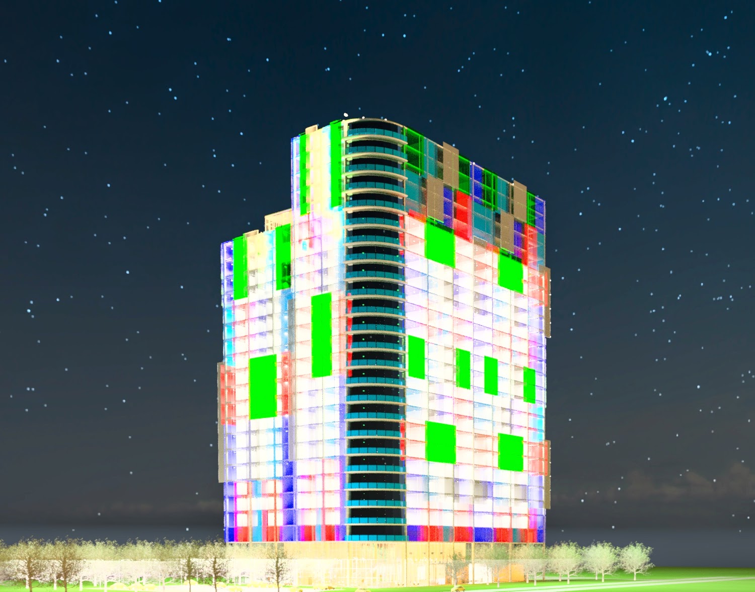


Final Results
Here you can see the final results from running the Dynamo program a few times.  Notice how the color pattern changes as well as the extrusion depth pattern changes each time that the program runs. 


Monday, March 24, 2014

ARCH 653 BIM Project 1

Arch 653 – Building Information Modeling Project 1
by: Kenny Jones


Overview

For this project, we were required to design a structure and create parametric relationships between different aspects of the building design. The simple structure seen below is a building concept that my structural design studio group and I created. It is an L shaped building located in Seattle, Washington, overlooking a lake on the south side. The west side (long leg side) of the building serves as a 25 story high rise living, while the south side (short leg side) serves as a 20 story high rise hotel with a restaurant on the base level. I have taken the basic layout and adjusted certain components (entrance corner, front and rear façade) in order to make the building more aesthetically pleasing.


Parametric Model:

Creating the parametric model was a very frustrating process initially. However after restarting about 6 or 7 times, I finally figured out a good way to go about creating my model. At first, I attempted to create three separate masses (west wing, east wing, south wing), but I ended up having way too many parameters to keep track of. Another issue was that I kept over constraining my model when aligning or assigning the many different parameters. Another issue I faced was, when assigning and changing parameters, the building would lengthen or shorten in the direction I did not want it to go (most likely due to the constraints I had placed on the masses). Therefore, I ended up just creating 2 major masses. The first mass was for the base 2 floors of the model. I used reference lines to create my base shape and extruded it up to a reference plane 40’ high. Next, I created a similar shape except there was a 10’ overhang on the North and East perimeters of the building, and the extrusion spanned from the 40’ up 360’ (24 floors at 15’). The next step was to parameterize my model. Since I did not want to have to change multiple variables each time to change the building, I decided to make everything move based on the base floor extrusion. I created 4 main parameters to change: Base Hotel Width, Base Hotel Length, Base Apartment Width, Base Apartment Length. Other parameters were made, but were linked to these main 4 in order the keep everything aligned and moving together. One major thing that I learned (about my 5th attempt) was that it was much easier to create all of my reference lines and testing parameters on the separate levels first before creating the extruded forms.


Building Façade

For my building façade, initially I had the idea of doing something similar to the image below. Creating this was simple using the divided surfaces method and the curtain panel pattern based family. I used a hexagon curtain panel, and used reference points and the create form button to create the panels. However, when I finally loaded them into my mass model, they imported to the divided surface (sometimes), but were typically distorted. I tried adjusting the surface gridlines, but nothing seemed to work. Finally, I decided to change my design after seeing a couple of different facades I was intrigued by.


I decided to do create a façade that had a series of colored panels that were offset at different depths from the face of the building. In addition, I wanted the façade to update with my building whenever the length, height, or width increased as well. The method I chose to accomplish this goal, was to create a large panel, made up of smaller panels whose depths were controlled through parameters.


First I started with a basic adaptive points model, where I created two reference levels. I placed four adaptive points (aligned) on the second reference level, created a surface panel, created a new material based on the “glass” material but changed the color, and finally I placed a parameter on the height between the reference levels (this was the only way it would let me change the height). I repeated this process for four more colored glass panels. Next I created my secondary panel which would host twodifferent colors. I repeated the same steps as above (minus the material change) except I also divided the surface of this panel into 4 quadrants. The next step involved importing two of the colors and placing them on opposite quadrants of the 4 quadrants of the divided surface to create a checkerboard look. Finally I selected the same colored glass panels and linked them to a parameter that would change that color’s offset height. This process was repeated for a variety of different patterns (using different colored panels). These 4 quadrant panels were then placed on a much larger panel with more than 4 quadrants, in the same manner (utilizing the adaptive points), until a proper “random pattern” look was achieved. The offset height parameters for the different colors were again linked in this model as well. This panel was my façade panel. In order to make the facade update with my building, I had to import it into my mass and attach the adaptive points to the divided surface nodes of the building face and then utilize the “repeater button” so that the panel repeated itself across the rest of the face. This ensured that even if the length of the mass increased, the façade would also increase the number of panels along the surface of the mass. This process worked perfectly everywhere except for the hotel side. For some reason, even with a void in place, Revit still divided the entire surface all the way up to the top of my mass. This was an issue since the hotel side was supposed to be 5 stories shorter than the rest of the building. In order to make the façade correct for this side of the building, I simply created a flat mass that only went up to the top of the hotel reference plane, aligned it with the building surface, divided its surface, placed the façade and repeated the pattern just as before. Before repeating, however, I linked the offset height parameters to ones in this model so that I could change them globally based on their colors: Navy Offset = 6’, Blue Offset = 4’, Green Offset = 2’, and Gray Offset =1’. This made it easier to change everything at once rather than selecting each individual panel.


After modeling this façade, I wanted to test out the sin wave panels that Saied Zarrinmehr showed us in class, so I tried to create a reflective curved façade for the south faces of the apartment and the hotel. In order to use these panels, a vertical reference line had to be drawn at the height I wanted my curve to be (in my case the entire building height). For these panels to move how I wanted them, I had to make certain adjustments. First I created another mass wall panel like I did for the hotel façade and divided the surfaces. Next, I placed a parameter that moved this mass a certain distance away from the building. Next, I imported the sin wave panels by placing the first two adaptive points on the vertical reference line and then on the wall mass face. From here I linked the parameters of the sin wave panel (amplitude and initial phase angle) to global parameters of the same name. I then “repeated” the panels horizontally for one level of the divided surface. This ensured that all panels at this level would act the same way (change the same angle, offset the same, etc.). I repeated this process all the way up my wall face, line by line, linking the parameters to the global parameters. Finally I changed the global amplitude and initial phase parameters to my liking in order to reflect the curve. I also changed the wall offset depth to be 5’ greater than the amplitude of the sin wave curves so that they would not come into contact with my building face.


The building facades that I created for this project were very tedious to set up, but overall, I was very pleased with the way that they turned out.


Project Model

Once my mass models were completed, I loaded them into a project and was then able to create the details of my building based on my parametrically based mass model. I created exterior curtain panel walls with mullions (since my façade was offset from the actual building), interior walls, doors, stairs, elevators and shafts, windows, balconies, ceilings, furnishings for the first floor, and even a site which included a parking lot, a street, trees, and the lake.

This part of the project took a while, simply due to furnishing the building and getting everything how I wanted it. I did not run into much trouble at this stage, other than my renderings taking a VERY long time. However, when it was all completed, I was very happy with my final results.

Overall, this being my first major project experience with Revit, I have to say that it is an awesome and very powerful program. Although, it can really frustrating when it does not let you do exactly what you want. Some improvements that would have helped me during my project would have been for Revit to tell/show me which member is over constrained when I get the “instances are over constrained” warning. Also, to show which instances are preventing the parameters from being “flexed”. I have definitely learned quite a bit (mostly from many mistakes) on how to use the basics of Revit to create a building using a mass, and how to utilize parameters.